dimensioning sheet metal parts solidworks Dimensions in a SOLIDWORKS drawing are associated with the model, and changes in the model are reflected in the drawing. Typically, you create dimensions as you create each part . Tulip Fabric Spray Paint gives your fabrics an instant burst of bold color for a total transformation in minutes! This nontoxic and eco-friendly formula comes with a pump nozzle for complete .
0 · SolidWorks sheet metal features
1 · SolidWorks sheet metal design
2 · SolidWorks sheet metal calculations
3 · SolidWorks rolling sheet metal dimensions
4 · SolidWorks dimensions
5 · SolidWorks dimension chart
6 · SolidWorks diagram dimensions
7 · SolidWorks 2013 sheet metal
Excellent quality 100% Polyester fabric, 58 inches wide. Perfect for dance and theatrical costumes.Check out our metallic turquoise fabric selection for the very best in unique or custom, handmade pieces from our fabric shops.
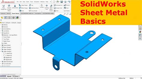
When designing sheet metal parts, the order preference for use of feature tools are as follows: 1. Use sheet metal features such as base-flanges, edge-flanges, miter flanges, etc. 2. Use the .
Dimensions in a SOLIDWORKS drawing are associated with the model, and changes in the model are reflected in the drawing. Typically, you create dimensions as you create each part .
Properties specific to sheet metal parts are calculated and displayed in the Cut-List Properties dialog box. Some of the properties that are calculated are based on the bounding box, the .In a drawing document, click Smart Dimension on the Dimensions/Relations toolbar. Select the Autodimension tab. Set properties in the Autodimension PropertyManager, and click .There are many factors that go into proper dimensioning: if it’s a sheet metal part you’ll need overalls and angles if it’s a hand machined part you’ll need a solid ordinate origin that is easy to edge-find to the consideration of importance: .
: Select your sketch in the feature tree then in the command manager select the base flange function from the sheet metal tab. : Add a dimension to set the depth of your profile in this case 10mm : Check override .Lets you specify sheet metal options. Available for all document types. Options vary depending on whether you are working with a part, assembly, or drawing. Properties specific to sheet metal .I've been looking for a drafting standard to show how to properly dimension a sheet metal jog's leg length for the purpose of calculating bend deductions and haven't found one. I have always . short demo on dimensioning a flat sheet metal part while holding as many of the dimensioning rules as we can in the process.please note this video as well as.
SolidWorks sheet metal features
When cuts are made into the flat pattern of a rolled sheet metal cylinder (or semi-cylinder), it is not always easy to extract model dimension data in a SOLIDWORKS drawing. Without proper design intent, detailing the flat pattern positions may not work.When designing sheet metal parts, the order preference for use of feature tools are as follows: 1. Use sheet metal features such as base-flanges, edge-flanges, miter flanges, etc. 2. Use the Insert Bends feature. 3. Use the Convert to Sheet Metal feature. When using the Insert Bends or Convert to Sheet Metal features, apply the features as earlyDimensions in a SOLIDWORKS drawing are associated with the model, and changes in the model are reflected in the drawing. Typically, you create dimensions as you create each part feature, then insert those dimensions into the various drawing views.
SolidWorks sheet metal design
Properties specific to sheet metal parts are calculated and displayed in the Cut-List Properties dialog box. Some of the properties that are calculated are based on the bounding box, the smallest rectangle in which the flat pattern can fit.In a drawing document, click Smart Dimension on the Dimensions/Relations toolbar. Select the Autodimension tab. Set properties in the Autodimension PropertyManager, and click .
There are many factors that go into proper dimensioning: if it’s a sheet metal part you’ll need overalls and angles if it’s a hand machined part you’ll need a solid ordinate origin that is easy to edge-find to the consideration of importance: hole . : Select your sketch in the feature tree then in the command manager select the base flange function from the sheet metal tab. : Add a dimension to set the depth of your profile in this case 10mm : Check override default parameters if you wish to adjust the thickness of your sheet metal part
Lets you specify sheet metal options. Available for all document types. Options vary depending on whether you are working with a part, assembly, or drawing. Properties specific to sheet metal parts are calculated and displayed in the Cut-List Properties dialog box.I've been looking for a drafting standard to show how to properly dimension a sheet metal jog's leg length for the purpose of calculating bend deductions and haven't found one. I have always dimensioned to outside control points and aligned the dimension to the jog leg as shown below.

china cnc lathe machining service factory
SolidWorks sheet metal calculations
The CableGuard CG-1000XL Demarcation Enclosure provides a UL Listed and .
dimensioning sheet metal parts solidworks|SolidWorks dimensions