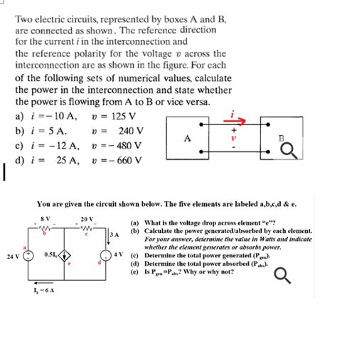
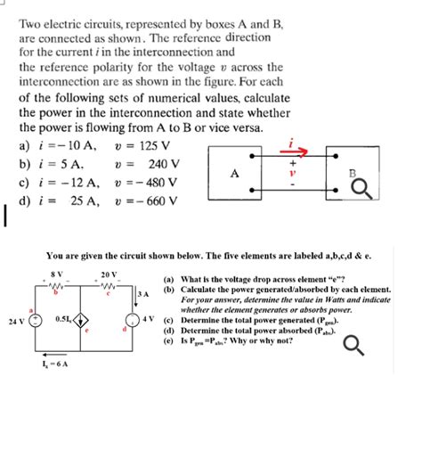
1.13 two electric circuits represented by boxes a and b There are 3 steps to solve this one. 1.13 Two electric circuits, represented by boxes A and B, are connected as shown in Fig. P1.130. The reference direction for the current i in the . The sizing requirements for pull boxes, junction boxes, handhole enclosures, and conduit bodies exist to prevent conductor insulation damage. Those requirements are in 314.28, and they apply to all conductors 4 AWG .
0 · two electrical circuits explained
1 · two electrical circuits box a
2 · two electric circuits represented by
3 · electrical circuits represented by box a
4 · box a and b electrical circuit
5 · 1.13 two electrical circuits explained
We produce standard and custom electrical enclosures that comply with UL standards to give you a high-quality, UL-listed enclosure. Freestanding , available with LSK JIC box
There are 3 steps to solve this one. 1.13 Two electric circuits, represented by boxes A and B, are connected as shown in Fig. P1.130. The reference direction for the current i in the .For each of the following sets of numerical values, calculate the power A B in the .Figure P1.13 i A | + | υ B 1.13 Two electric circuits, represented by boxes A and B, .
Two electric circuits, represented by boxes A and B, are connected as shown. The reference direction for the current i in the interconnection and the reference polarity for the voltage v across the interconnection are as shown in the figure.
Two electric circuits, represented by boxes A and B, are connected as shown in the figure below. The reference direction for the current i in the interconnection and the reference polarity for the voltage v across the interconnection are as . For each of the following sets of numerical values, calculate the power in the interconnection and state whether the power is flowing from A to B or vice versa. 1. a) i = 6 A , .a) Calculate the power at the terminals and state whether the power is being absorbed or delivered by the element in the box. b) Given that the current is due to electron flow, state .
For each of the following sets of numerical values, calculate the power A B in the interconnection and state whether the power is flowing from A to B or vice versa. a.i6A, =30 V b.i-8A, = -20 V c.i4A, =-60 V d.i-9A, -40 V If the interconnection in .Figure P1.13 i A | + | υ B 1.13 Two electric circuits, represented by boxes A and B, are connected as shown in Fig. P1.13 Q. The reference direction for the current i in the interconnection and the reference polarity for the voltage v across the .Two electric circuits, represented by boxes A and B, are connected. The reference direction for the current i in the interconnection and the reference polarity for the voltage v across the inter .5.Two electric circuits,represented by boxes A and B,are connected as shown in Fig.5. The reference direction for the current i in the interconnection and the reference polarity for the.
Three capacitors A, B and C are charged as follows: A = 10 uF, 100 V; B = 15 uF, 150 V and C = 25 uF, 200 V. They are connected in parallel with terminals of like polarity together. What is the voltage across the combination? Three resistors .
two electrical circuits explained

There are 3 steps to solve this one. 1.13 Two electric circuits, represented by boxes A and B, are connected as shown in Fig. P1.130. The reference direction for the current i in the interconnection and the reference polarity for the voltage v across the interconnection are as shown in the figure.Two electric circuits, represented by boxes A and B, are connected as shown. The reference direction for the current i in the interconnection and the reference polarity for the voltage v across the interconnection are as shown in the figure.
manufacturer of cnc machine in india
Two electric circuits, represented by boxes A and B, are connected as shown in the figure below. The reference direction for the current i in the interconnection and the reference polarity for the voltage v across the interconnection are as shown in the figure. For each of the following sets of numerical values, calculate the power in the interconnection and state whether the power is flowing from A to B or vice versa. 1. a) i = 6 A , v = 30 V 2.a) Calculate the power at the terminals and state whether the power is being absorbed or delivered by the element in the box. b) Given that the current is due to electron flow, state whether the electrons are entering or leaving terminal 2. c) Do the electrons gain or lose energy as they pass through the element in the box?
For each of the following sets of numerical values, calculate the power A B in the interconnection and state whether the power is flowing from A to B or vice versa. a.i6A, =30 V b.i-8A, = -20 V c.i4A, =-60 V d.i-9A, -40 V If the interconnection in Fio.Figure P1.13 i A | + | υ B 1.13 Two electric circuits, represented by boxes A and B, are connected as shown in Fig. P1.13 Q. The reference direction for the current i in the interconnection and the reference polarity for the voltage v across the interconnection are as shown in the figure.Two electric circuits, represented by boxes A and B, are connected. The reference direction for the current i in the interconnection and the reference polarity for the voltage v across the inter connection are as shown.
two electrical circuits box a
5.Two electric circuits,represented by boxes A and B,are connected as shown in Fig.5. The reference direction for the current i in the interconnection and the reference polarity for the.Three capacitors A, B and C are charged as follows: A = 10 uF, 100 V; B = 15 uF, 150 V and C = 25 uF, 200 V. They are connected in parallel with terminals of like polarity together. What is the voltage across the combination? Three resistors are connected as shown in the diagram. Through the resistor 5 ohm, a current of 1 ampere is flowing.
There are 3 steps to solve this one. 1.13 Two electric circuits, represented by boxes A and B, are connected as shown in Fig. P1.130. The reference direction for the current i in the interconnection and the reference polarity for the voltage v across the interconnection are as shown in the figure.Two electric circuits, represented by boxes A and B, are connected as shown. The reference direction for the current i in the interconnection and the reference polarity for the voltage v across the interconnection are as shown in the figure.
Two electric circuits, represented by boxes A and B, are connected as shown in the figure below. The reference direction for the current i in the interconnection and the reference polarity for the voltage v across the interconnection are as shown in the figure.
For each of the following sets of numerical values, calculate the power in the interconnection and state whether the power is flowing from A to B or vice versa. 1. a) i = 6 A , v = 30 V 2.a) Calculate the power at the terminals and state whether the power is being absorbed or delivered by the element in the box. b) Given that the current is due to electron flow, state whether the electrons are entering or leaving terminal 2. c) Do the electrons gain or lose energy as they pass through the element in the box?

For each of the following sets of numerical values, calculate the power A B in the interconnection and state whether the power is flowing from A to B or vice versa. a.i6A, =30 V b.i-8A, = -20 V c.i4A, =-60 V d.i-9A, -40 V If the interconnection in Fio.Figure P1.13 i A | + | υ B 1.13 Two electric circuits, represented by boxes A and B, are connected as shown in Fig. P1.13 Q. The reference direction for the current i in the interconnection and the reference polarity for the voltage v across the interconnection are as shown in the figure.
Two electric circuits, represented by boxes A and B, are connected. The reference direction for the current i in the interconnection and the reference polarity for the voltage v across the inter connection are as shown.
two electric circuits represented by

5.Two electric circuits,represented by boxes A and B,are connected as shown in Fig.5. The reference direction for the current i in the interconnection and the reference polarity for the.

man of steel movie box office mojo
mallaby sheet metal
$9.99
1.13 two electric circuits represented by boxes a and b|electrical circuits represented by box a