sheet metal box flat pattern This is quick & simple tutorial for solidworks beginners starting working with sheet metal.
$39.99
0 · solidworks sheet metal flat pattern
1 · sheet metal flat pattern
2 · sheet metal box template
3 · sheet metal box size chart
4 · sheet metal box patterns
5 · sheet metal box layout
6 · sheet metal box dimensions
7 · how to make sheet metal boxes
$79.99

If you can't visualize how the flat pattern for a box should look with sheet metal, find an old shoe box or cereal box and unfold it. The patterns for a cardboard box will look very similar to what .Sheet Metal Properties. Properties specific to sheet metal parts are calculated and displayed in the Cut-List Properties dialog box. Some of the properties that are calculated are based on the . Sheet Metal Box. What I have here is a basic 12″ x 12″ x 12″ box that you’ve probably seen a few times if you’ve followed these sheet metal .
Sheet Metal flat pattern calculator can be used to calculate sheet metal flat length as per required sheet metal bend part. Calculation Example: The flat pattern calculation (FPC) is used in sheet metal fabrication to determine the amount of material required to create a specific shape. It is given . This is quick & simple tutorial for solidworks beginners starting working with sheet metal.In a recent support case, we were asked if sheet metal flat pattern info, specifically the flat pattern area, can be shown in a SOLIDWORKS drawing bill of material. After a little research it turns out that the answer is surprisingly yes .
Using the SOLIDWORKS Sheet Metal Bounding box you can automate the creation of flat pattern data in your related drawing.
solidworks sheet metal flat pattern
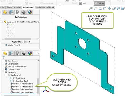
You can modify the parameters of Flat-Pattern1 to control how the part bends, to enable or disable corner options, and to control the visibility of the bend region in the flattened sheet metal part. . This webinar focuses on tips you need to know to work with sheet metal flat patterns in Onshape, including: creating features, exporting to DXF/DWG, and more.In Sheet Metal or Fabrication Industry Flat Pattern making is useful for forming various shapes such as Conical Shapes, Box Shapes, Pipe Shapes, Transition Shapes such as Square to Round or Round to Square, or any complex shapes used for various applications in various Industry. This is quick & simple tutorial for solidworks beginners starting working with sheet metal. DXF ready for metal fabricator shop!Follow simple steps to learn .
Inventor Professional 2018.2.3 64 bit on Windows 10 I will sometimes create a sheet metal part from a derived solid to simplify the development of a weldment containing many interrelated sheet metal parts (derived from the same solid.) I have run into a problem whereby the sheet metal flat pattern will not show in a flat pattern drawing view. This happens .
sheet metal flat pattern
I have a iLogic code here (See below), that I copied from on one of the forums here, for creating flat patterns from a sheet metal part template. It is working great in automatically generating a flat pattern but is there a way to update/add in the code to delete the old flat pattern and create a ne. Hi. I'm having an issue with a flat pattern not generating. After a quick check of the common reasons for failure, the material type and thickness seem to match the sheet metal default being used. The design intent got pretty murky through the development of the assmbly, and I just need a flat pattern to cut this part "Back plate_sheave box.ipt".
Flat Pattern Area Calculation. This calculator provides the calculation of the flat pattern area of a sheet metal part. Explanation. Calculation Example: The flat pattern area is the area of the sheet metal before it is bent or formed into a three-dimensional shape. It is important to calculate the flat pattern area accurately in order to avoid .
SolidWorks Sheet metal Tutorial Switch Box we will learn Base flange, Edge Flange, Corner, hemming, Vent,unfold, fold, extruded cut, mirror, Simple Hole, flatten the parts, how to save as 2D drawing f. Hello,I have a problem resolving a sheet metal flat pattern situation.Capture-2 shows the complete corner with on 2 sides a flange with radius from 20mm, and also the corner with a radius from 20mm.The problem is within the corner with R=20 I modeled it as a solid box and made fillets on the 2 sides and the corner, then i used Shell and got the correct end product.
The Flat-Pattern1 feature is intended to be the last feature in the folded sheet metal part. All features before Flat-Pattern1 in the FeatureManager design tree appear in both the folded and flattened sheet metal part. All features after Flat-Pattern1 appear only in the flattened sheet metal part.. Improvements to flattening sheet metal parts make flattening succeed for complex .bnemec wrote: ↑ Thu Jul 01, 2021 7:03 pm I've learned that my memory will sometimes mix things together to create something that never happened, but I thought that I saw that Solidworks Bounding Box sketch in the sheet metal Flat Pattern Feature could be configured with a custom offset. The reason is that forces out of my control always add a little to the width and length of .The following practices apply for sheet metal iParts: When you create a drawing view for a sheet metal iPart, you can select an explicit iPart member on the Model tab of the Drawing View dialog. If a flat pattern is available in an iPart member file, the Flat Pattern option is enabled in the Drawing View dialog.
sheet metal fabrication books free download
“Transfers the sheet metal and flat pattern information from the original part to the mirrored part such as fixed face, grain direction, bend lines, and bounding box. Some sheet metal features are not supported for mirroring or inserting, including lofted bends, swept flanges, welded corners, and non-linear edge flanges and hems.” .In the Drawing View dialog box, select a sheet metal component as File. In the Sheet Metal View area, select Flat Pattern view. . on the ribbon click Sheet Metal tab Flat Pattern panel , click Create Flat Pattern. The flat pattern is created, and displays. In the browser, double-click the Folded Model node to return to the folded model state or,
I need help importing the sheet metal bounding box (flat pattern) dimensions into custom properties. . I am creating a Bill of Materials for sheet metal prototypes to be cut on a CNC plasma, but to help the guys in the shop, I decided to include the approximate lengthXwidth to give them a better understanding of the parts to be cut, without .The Flat-Pattern1 feature is intended to be the last feature in the folded sheet metal part. All features before Flat-Pattern1 in the FeatureManager design tree appear in both the folded and flattened sheet metal part. All features after Flat-Pattern1 appear only in the flattened sheet metal part.. Improvements to flattening sheet metal parts make flattening succeed for complex .Use the Flat Pattern Preview tool to open a window with a preview of the sheet metal body in an unbent state. The preview is closed when you add or redefine features in a design. . • Bounding Box Dimensions —Toggles the display of the length and width dimensions of .
One of the biggest benefits of Onshape’s Simultaneous Sheet Metal features is the ability to see the flat pattern update in real time as you make changes to your sheet metal part. But what about creating drawings of that flat pattern? Let’s .Hello again. I'm working on a box cardboard using sheet metal tools (shout out to u/productsdesignonline for excellent tutorial on the subject to get me going in the right direction) and need to make some edits to flaps in the, but they're inside the box.. I could do a section analysis to see what I need to see, but it's still easier if the box is flattened or unfolded. Hi there, As the title states. I can't figure it out. I have this problem I can't figure out. I created a rolled sheet with the Contour flange option. I then proceed the Flat Pattern it. Here, I create cut out/s. I get the usual message that it is only going to be implemented on the Flat Pattern. When I export it to a Drawing, it all is fine. I have a sheet metal box with a chamfer I added to one side in the folded version of the model. I want the chamfer to appear in the folded model only, but the chamfer shows up in the flat pattern as a twisted and distorted edge. How do I exclude a feature I intend to be created only after folding .
sheet metal fabricated rockmart ga
Conversion of a sheet metal part to a standard part automatically deletes the sheet metal flat pattern. Any time you delete a flat pattern in a sheet metal part, you also delete all of the flat pattern views in associated drawings. Create Flat Pattern calculates the material and layout required to flatten a 3D sheet metal model.Use the Flat Pattern tool to automatically create a flattened version of a sheet metal part and prepare the model for manufacture. The Flat Pattern feature remains the last feature in the Model Tree and maintains the flat model view. . After you create a Flat Pattern feature, use the Bounding Box Dimensions command on the View tab to toggle .Need Sheet Metal Cut Patterns? WH Rulers Provides More Than 20 Patterns, Band Cut Charts, Insulation Miter Cut Sharts & More. Try Out Sheetmetal Flat Pattern Book Now!Use the Flat Pattern Preview tool to open a window with a preview of the sheet metal model in an unbent state. The preview is suppressed when you add or redefine features in a design. . • Create Instance —Opens the New Instance dialog box to automatically create a Family Table instance of the flat pattern.
While working in the Sheet Metal environment, you can set options on the Flat Pattern Treatments page of the Options dialog box to automatically clean up the flat pattern. The options on the Flat Pattern Treatments tab control corner treatments, simplify B-splines in the model to arcs and lines, and remove the system-generated bend relief. Create sheet metal drawings in SOLIDWORKS twice as fast. We can add a flat pattern view automatically, show the bounding box + add dimensions. +31 85 0653 776 . Show the bounding box for a flat pattern view. Drew has lots of settings to create the perfect flat pattern view. In the image below, you see that we rotate the view so the long edge .In a sheet metal part, create a new configuration. In the FeatureManager design tree, do one of the following: Right-click Flat-Pattern and select Unsuppress.; Select Process-Bends and all of the features after it. Click Edit > Suppress > This Configuration to .

sheet metal box template
NEMA 3R and 4X rated battery box outdoor enclosures by DDB Unlimited protect important electronics from extreme elements, climates and environments.
sheet metal box flat pattern|sheet metal box patterns