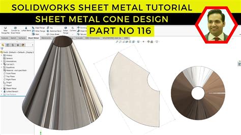
creating sheet metal parts with conical faces To create a sheet metal part with conical faces: Create a thin feature part with one or more conical faces: Any adjacent planar and conical faces must be tangent. There are several possible defects that can occur in drawn sheet-metal parts, some of them include: Wrinkles: They occur when the metal is stretched beyond its elastic limit, causing the surface of the metal to become folded or creased.
0 · solidworks sheet metal conical
1 · solidworks sheet metal bends
2 · sheet metal with conical faces
When splicing wires, an accessible electrical junction box box is necessary to enclose the spliced wires, thus the trade name is electrical enclosure. This list shows various electrical boxes and displays the box name and describes the typical application.
Select a planar face tangent to the conical face as the fixed face. The fixed edge remains in place when the part is flattened. The name of the edge is displayed in the Fixed Face or Edge box. .

To create a sheet metal part with conical faces: Create a thin feature part with .To create a sheet metal part with conical faces: Any adjacent planar and conical .Parts with conical faces can also be made of sheet metal. To create a sheet metal .To create a sheet metal part with conical faces: Create a thin feature part with one or more conical faces: Any adjacent planar and conical faces must be tangent.
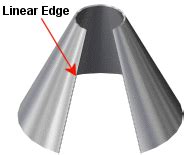
To create a sheet metal part with conical faces: Any adjacent planar and conical faces must be tangent. At least one end face of any conical face must have at least one linear edge. Click .Parts with conical faces can also be made of sheet metal. To create a sheet metal part with conical
Create sheet metal parts by converting existing parts, extruding sketch curves (including arcs and splines to create rolled sheet metal), or thickening faces or sketches. This video will show you a simple process for making conical sheet metal components, that will unfold, in Autodesk Fusion 360
Autodesk Fusion 360 does not have a specific command that will allow the creation of conical sheet metal components, but with a little creativity, the process is easy! The first step is to create a constrained sketch of the .
The steps to make an unfolding diagram are as follows. 1. Draw the main view and fill in the top truncation to form a complete cone. 2. Make a cone surface line by dividing the .The sheet metal design process involves conceptualizing, drawing, and creating detailed plans for cutting, shaping, and joining metal. It’s all about turning metal sheets into durable, functional, .The first step in fabricating a cone from sheet metal is determining the dimensions of the cone you want to create. This includes the base diameter, top diameter (if it's a frustum), and the height .
Select a planar face tangent to the conical face as the fixed face. The fixed edge remains in place when the part is flattened. The name of the edge is displayed in the Fixed Face or Edge box. Set the Bend Radius. Select Ignore beveled faces to exclude chamfers from being converted into sheet metal bends.To create a sheet metal part with conical faces: Create a thin feature part with one or more conical faces: Any adjacent planar and conical faces must be tangent.To create a sheet metal part with conical faces: Any adjacent planar and conical faces must be tangent. At least one end face of any conical face must have at least one linear edge. Click Insert Bends or Insert > Sheet Metal > Bends. The Bends PropertyManager appears. Select a linear edge on an end face of a conical face as the fixed edge.Parts with conical faces can also be made of sheet metal. To create a sheet metal part with conical
Create sheet metal parts by converting existing parts, extruding sketch curves (including arcs and splines to create rolled sheet metal), or thickening faces or sketches.This video will show you a simple process for making conical sheet metal components, that will unfold, in Autodesk Fusion 360 Autodesk Fusion 360 does not have a specific command that will allow the creation of conical sheet metal components, but with a little creativity, the process is easy! The first step is to create a constrained sketch of the desired conical component wall. The steps to make an unfolding diagram are as follows. 1. Draw the main view and fill in the top truncation to form a complete cone. 2. Make a cone surface line by dividing the base circle into a number of equal parts, in this case 12 equal parts, to obtain 1, 2, ., 7 points, from these points to draw a vertical line upwards, and intersect the base circle orthographic .
The sheet metal design process involves conceptualizing, drawing, and creating detailed plans for cutting, shaping, and joining metal. It’s all about turning metal sheets into durable, functional, and aesthetic products for various industries, from aerospace to automotive.The first step in fabricating a cone from sheet metal is determining the dimensions of the cone you want to create. This includes the base diameter, top diameter (if it's a frustum), and the height of the cone.
Select a planar face tangent to the conical face as the fixed face. The fixed edge remains in place when the part is flattened. The name of the edge is displayed in the Fixed Face or Edge box. Set the Bend Radius. Select Ignore beveled faces to exclude chamfers from being converted into sheet metal bends.To create a sheet metal part with conical faces: Create a thin feature part with one or more conical faces: Any adjacent planar and conical faces must be tangent.To create a sheet metal part with conical faces: Any adjacent planar and conical faces must be tangent. At least one end face of any conical face must have at least one linear edge. Click Insert Bends or Insert > Sheet Metal > Bends. The Bends PropertyManager appears. Select a linear edge on an end face of a conical face as the fixed edge.Parts with conical faces can also be made of sheet metal. To create a sheet metal part with conical

Create sheet metal parts by converting existing parts, extruding sketch curves (including arcs and splines to create rolled sheet metal), or thickening faces or sketches.
solidworks sheet metal conical
This video will show you a simple process for making conical sheet metal components, that will unfold, in Autodesk Fusion 360 Autodesk Fusion 360 does not have a specific command that will allow the creation of conical sheet metal components, but with a little creativity, the process is easy! The first step is to create a constrained sketch of the desired conical component wall.
The steps to make an unfolding diagram are as follows. 1. Draw the main view and fill in the top truncation to form a complete cone. 2. Make a cone surface line by dividing the base circle into a number of equal parts, in this case 12 equal parts, to obtain 1, 2, ., 7 points, from these points to draw a vertical line upwards, and intersect the base circle orthographic .The sheet metal design process involves conceptualizing, drawing, and creating detailed plans for cutting, shaping, and joining metal. It’s all about turning metal sheets into durable, functional, and aesthetic products for various industries, from aerospace to automotive.

norinco 7.62x39mm steel core yellow box on the armslist
WESTFIELD SHEET METAL WORKS in Kenilworth, reviews by real people. Yelp is a fun and easy way to find, recommend and talk about what’s great and not so great in Kenilworth and beyond.
creating sheet metal parts with conical faces|sheet metal with conical faces