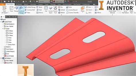
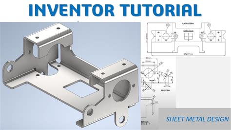
sheet metal inventor Learn how to create, edit, and flatten sheet metal parts in Inventor. Find out how to use templates, defaults, fasteners, features, and tools for sheet metal design and manufacturing. Metallic fibers are manufactured fibers composed of metal, metallic alloys, plastic-coated metal, metal-coated plastic, or a core completely covered by metal. [1] Having their origin in textile and clothing applications, gold and silver fibers have been used .
0 · sheet metal loft in inventor
1 · sheet metal inventor tutorial pdf
2 · sheet metal inventor tutorial
3 · sheet metal drawing in inventor
4 · inventor unfold sheet metal
5 · inventor sheet metal thickness
6 · inventor convert to sheet metal
7 · inventor change sheet metal thickness
A junction box is not a special type of box but any standard electrical box used to enclose wire splices. The most commonly used box for junctions is a 4-inch square box (either metal or strong plastic), which offers ample space for making wire connections with multiple wires or .
Inventor 101: Sheet Metal Basics. 376 Likes. 93,281 Views. 2018 Aug 6. In part 22 of the Autodesk Inventor 101: The Basics series, we'll take a look at how to use the basic functionality of. My affiliate link for a free trial - https://goo.gl/qbZK5n A quick start guide on how sheet metal works in Autodesk Inventor, very basic but covers the initial setup of styles and how to.Add holes to sheet metal parts in Inventor. Inventor.Learn how to create, edit, and flatten sheet metal parts in Inventor. Find out how to use templates, defaults, fasteners, features, and tools for sheet metal design and manufacturing.
Autodesk Inventor now has integrated sheet metal tools that make it easier to design with sheet metal. In this Inventor 101 video, we’ll take you through all of the sheet metal design basics you’ll need to know to get started .You can add, edit, and delete bends. Bend features can join sheet metal faces that do not touch. When you select edges on sheet metal features, you add material to the model using the bend radius and material thickness defined by .Learn how to create, edit, and document sheet metal parts in Autodesk Inventor software. A sheet metal part is a part fabricated from a uniformly thick material that can be displayed as a folded model or a flat pattern. To clarify - While part is active, go to Sheet metal ribbon > Setup > Sheet metal defaults > Click pencil tip next to drop down for sheet metal rule > Sheet tab > thickness > highlight the current number (eg 0.5mm).

AUTODESK INVENTOR Sheet Metal Tutorial (Full Course 2hr:55min) playListhttps://www.youtube.com/playlist?list=PLx-VY2mDlK2GxztfldvlGnksvjXF2K0pLvideo-tutori.In Inventor, a sheet metal part starts out as a flat piece of metal with a consistent thickness. In this tutorial, you set sheet metal defaults and create a 2D sketch for sheet metal design. On the . Learn Autodesk inventor how to use sheet metal for beginner(DONATE) Support us to buy tools and software: https://www.paypal.com/paypalme/mufasucad#inventor#. I recently upgraded to IV2009PRO. This is my first time using the sheetmetal module (since the upgrade). I am having trouble changing the material thickness. I just created a simple bent part (no legacy daata). Typically, I .
Inventor 2022 TutorialInventor 2022 Tutorial #230 | 3D Sheet Metal Design#inventor2022, #inventortutorial, #cadcamsolutions-----.When specifying face in Sheet Metal, closed loop detection is now improved to make it easier to select geometry from a sketch, especially in situations where multiple profiles are overlapping. . An Inventor® Ideas submission. Sketch Pattern Performance. This is a general improvement for sketch driven pattern, not only for compute, but also .
Two questions about sheet metal rules:The first: There are two rules for unfold sheets, the first is K-Factor, which is well known, and the second method is the bend Compensation.What is the Bend Compensation rule in a simple way?And the second question:When calculating the key-factor, why is there a bend deduction method, even though . Inventor Forum > Sheet metal tabs; Inventor. Community Forums; Inventor Forum Welcome to Autodesk’s Inventor Forums. Share your knowledge, ask questions, and explore popular Inventor topics. cancel. Turn on suggestions. Auto-suggest helps you quickly narrow down your search results by suggesting possible matches as you type. . Làm thế nào để trãi tôn tấm trong Inventor Sheet Metal - Inventor cho người mới bắt đầuCảm ơn các bạn đã theo dõi video. Chúc các bạn 1 ngày vui khỏe.Rất vu. Check out more tips and articles here www.ketiv.com/blog/In this week's video, Jonathan Landeros of KETIV Technologies shows how you can create a sheet metal.
I mistakenly created a part using the sheet metal template and now I need to creat multiple bodies. Is there a way to convert a part from the sheet metal template to standard? I tried Manage->create part using the existing body but I can't access model history or features in the new part. I can continue to create the new bodies in this new part but I was curious about . If so, it is good practice to create a sheet metal style and not just uncheck use thickness from rule and alter the thickness. Instead use the pencil icon and create sheet metal default for your company thickness. That way you have a dedicated style for each thickness of material and can control relief shapes and bend rads per thickness. Understanding Bend Allowance and Bend Deduction in Inventor; Calculating Bend Allowance and Setback Example; How to check a K-factor of sheet metal part in Inventor; Determining correct K factor within sheet metal environment of Inventor; Flat Patter of Sheet Metal Part changed size after KFactor were changed in Inventor
Try and keep all your sheet metal sketches on the same plane. Sketch 1 was on the XY plane - make Sketch2 on the XY plane as well. Keep it simple. Test frequently. If you repeat the above steps, when you draw the circle, place a "Point" at the center of the circle. Create the cut feature. Extract the Cut feature as a sheet metal punch iFeature. Work with sheet metal every day all day, I prefer making models that look like they will when they are made by the processes the shop I design for uses. Pretty does not do a thing for me. You seem to have some industry knowledge and you certainly know Inventor. Hi All, I am into an ilogic to get extents of part and sheet metal from Assembly. I have ended up in a logic in which i can get the part extents from Assembly but the value of Sheet metal extents are different. For this I am running a seperate ilogic to get sheetmetal dimensions. I tried options to combine these two ilogic to run a single rule for an assembly comprising of .
Inventor Forum > Sheet Metal; Inventor. Community Forums; Inventor Forum Welcome to Autodesk’s Inventor Forums. Share your knowledge, ask questions, and explore popular Inventor topics. cancel. Turn on . I have found that if you intend to create something like a "tank" to hold fluids, Inventor works quite well, providing you aren't trying to do it inside of the sheet metal environment. First create a sheet metal part. If needed a flat panel layout (not really necessary). Save the part. Open a new weldment Assembly. Place the sheet metal part . With the release of Inventor 2025, Autodesk has started to move away from feature creation dialog boxes to Properties panel s for Sheet Metal features. As with the standard features in a part modeling environment, the transition will likely take several releases, but I am excited that it has started.The following practices apply for sheet metal iParts: When you create a drawing view for a sheet metal iPart, you can select an explicit iPart member on the Model tab of the Drawing View dialog. If a flat pattern is available in an iPart member file, the Flat Pattern option is enabled in the Drawing View dialog.
sheet metal bending 101
I'm wondering if there is an easy way to convert this standard Inventor 2015 part to a sheet metal part so I can create a flat pattern. I've had some light sheet metal training years ago, mostly unused and forgotten. The part was created from a thickened surface quilt in a multibody solid. I'm recreating a complex assembly from 2D drawings from the 70's and many . Hello I have a sheet metal part. It is a machine door with four edge flanges. I have mirrored this part. The origin part has flat pattern while the mirrored creates the folded pattern. It still folded even when origin is in flat pattern. Please advise does it mean I . I need a little help. I am trying to produce a sink bowl that is 6”tall inside x 10” wide inside x 10” wide inside in 20 ga stainless steel sheet. I need to produce a corner flat pattern that actually represents a 1” radius that can be welded. Now this was drawn as a non- sheet metal part, then extruded and then shelled to produce the look of the part I need. I cut a slit in .
Inventor 10 XP SP2 "Peter" wrote in message news:[email protected]. Is it possible to create a "pipe" as a sheet metal part? I would like to create a part looking like the one attached - a 2 mm sheet rolled with an outer diameter of 304 mm (never mind Extrusion3 - it is the initial creation of the cylindrical shape .Create a Sheet Metal Part Template . On the ribbon, click Sheet Metal tab Setup panel Sheet Metal Defaults. Optionally, override the Material, Thickness, or Unfolding Rule. . Save the file in the Autodesk\Inventor [version]\Templates folder, or a subfolder of Templates. The newly created template is available in the New dialog box.
https://www.youtube.com/channel/UCjd_zIvYtQymk0dPx3vTJcA/joinYou Can Support our Channel for more tutorials.in this tutorial video we will .Create and Name a New Sheet Metal Rule. To create a sheet metal rule, copy the supplied Default rule (or an existing rule) and make and save changes to the selections and values on all three tabs.. Click Manage tab Styles and Standards panel Styles Editor to open the Style and Standard Editor dialog box.; Click the expand/collapse “+” to the left of the Sheet Metal Rule .Starting a New Sheet metal File 1. To start a new sheet metal file, click Get Started Launch > New on the ribbon. 2. On the Create New File dialog, click the Sheet Metal.ipt icon, and then click Create. Setting the Parameters of the Sheet Metal part 1. To set the parameters, click Sheet Metal > Setup > Sheet Metal Defaults on the ribbon; the Sheet Learn Autodesk Inventor sheet metal tutorial how to create cone object, check it out!!!Don't forget guys, if you like our videos please "Subscribe", "Like", .
sheet metal loft in inventor
sheet metal inventor tutorial pdf
sheet metal inventor tutorial

Wire ID is essential for safety and efficiency, and adhering to wire color codes is an integral aspect. Learn about NEC wire color code standards, 3-Phase color codes.
sheet metal inventor|inventor sheet metal thickness