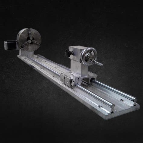
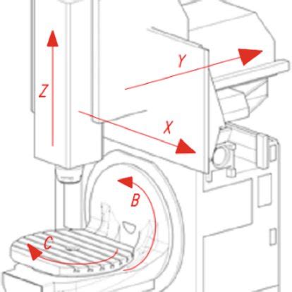
cnc machine axis movement During key concept number one, we discussed how end points for axis motion are commanded utilizing the rectangular coordinate system. During that presentation, however, we .
• Wireway exceeding 72 inches in length has two overlapping covers • Variety of fittings allow runs which can change direction, junction and terminate • Standard wireway connectors (sold .
0 · cnc with rotary axis
1 · cnc machine axis locations diagram
2 · cnc machine axis direction
3 · cnc axis explained
4 · cnc axis chart
5 · axis identification in cnc machine
6 · 4 axis cnc milling machines
7 · 4 axis cnc machine cost
A junction box provides a code-approved place to house wire connections, whether for outlets, switches, or splices. Here's how to install one.
To achieve ultimate precision in CNC machining, linear and rotary axes play a crucial role. Linear axes provide linear movement in addition to the primary X, Y, and Z axes, enabling versatility . Almost every CNC machine uses a Cartesian coordinate system based on an X, Y, and Z-axis. The coordinate system allows the machine to identify locations, move in specific .
As a foundational axis in CNC machining, the X-axis facilitates lateral movement, extending left and right across the machine’s horizontal plane. This axis is critical for . Nearly all CNC machine uses a Cartesian coordinate system based on an X, Y, and Z-axis. This system allows a machine to move in a specific direction along a specific plane. . There are three primary axes on a CNC lathe: the X-axis, Z-axis, and sometimes the C-axis. X-Axis: The X-axis is the horizontal axis that runs parallel to the bed of the lathe. It controls the movement of the cutting tool .
During key concept number one, we discussed how end points for axis motion are commanded utilizing the rectangular coordinate system. During that presentation, however, we . In this article, we discuss linear and rotary axes, concepts that introduce us to the different CNC machine axis configurations in various systems. We will explore the various types of CNC machines based on the number of axes they have, ultimately covering whether systems with more CNC machine axis counts are better.
To achieve ultimate precision in CNC machining, linear and rotary axes play a crucial role. Linear axes provide linear movement in addition to the primary X, Y, and Z axes, enabling versatility and detailed control over cutting operations.
Almost every CNC machine uses a Cartesian coordinate system based on an X, Y, and Z-axis. The coordinate system allows the machine to identify locations, move in specific directions and establish positions in a three-dimensional space. As a foundational axis in CNC machining, the X-axis facilitates lateral movement, extending left and right across the machine’s horizontal plane. This axis is critical for positioning both the cutting tool and the workpiece with precision. Nearly all CNC machine uses a Cartesian coordinate system based on an X, Y, and Z-axis. This system allows a machine to move in a specific direction along a specific plane. Reduce the Cartesian system to its basics, and you have a familiar number line.
There are three primary axes on a CNC lathe: the X-axis, Z-axis, and sometimes the C-axis. X-Axis: The X-axis is the horizontal axis that runs parallel to the bed of the lathe. It controls the movement of the cutting tool along the length of the workpiece.
During key concept number one, we discussed how end points for axis motion are commanded utilizing the rectangular coordinate system. During that presentation, however, we were only concerned with describing how the CNC machine determines the end point position for . The number of axes in a CNC machine correlates with its capabilities: 3-axis: Suitable for basic milling and 2.5D machining; 4-axis: Adds rotational capability, allowing for more complex geometries; 5-axis: Enables simultaneous movement in all three linear axes plus two rotational axes, ideal for complex 3D shapes and undercuts Four- and five-axis CNC milling machines have one or two rotating axes in addition to the three axes that move the table. The figure above shows the main control parts of a CNC mill, including the human-machine interface (computer), controller, amplifier, encoder, motor, ball screw, and guide rail. A Critical Element of CNC Machining is its Axis Configuration, which directly affects the machine’s Capabilities, Complexity, and Applications. From simple 3 Axis Setups to Advanced 8 Axis Configurations, each setup offers unique capabilities suited to .
In this article, we discuss linear and rotary axes, concepts that introduce us to the different CNC machine axis configurations in various systems. We will explore the various types of CNC machines based on the number of axes they have, ultimately covering whether systems with more CNC machine axis counts are better.
To achieve ultimate precision in CNC machining, linear and rotary axes play a crucial role. Linear axes provide linear movement in addition to the primary X, Y, and Z axes, enabling versatility and detailed control over cutting operations. Almost every CNC machine uses a Cartesian coordinate system based on an X, Y, and Z-axis. The coordinate system allows the machine to identify locations, move in specific directions and establish positions in a three-dimensional space. As a foundational axis in CNC machining, the X-axis facilitates lateral movement, extending left and right across the machine’s horizontal plane. This axis is critical for positioning both the cutting tool and the workpiece with precision.
Nearly all CNC machine uses a Cartesian coordinate system based on an X, Y, and Z-axis. This system allows a machine to move in a specific direction along a specific plane. Reduce the Cartesian system to its basics, and you have a familiar number line.
There are three primary axes on a CNC lathe: the X-axis, Z-axis, and sometimes the C-axis. X-Axis: The X-axis is the horizontal axis that runs parallel to the bed of the lathe. It controls the movement of the cutting tool along the length of the workpiece.
During key concept number one, we discussed how end points for axis motion are commanded utilizing the rectangular coordinate system. During that presentation, however, we were only concerned with describing how the CNC machine determines the end point position for . The number of axes in a CNC machine correlates with its capabilities: 3-axis: Suitable for basic milling and 2.5D machining; 4-axis: Adds rotational capability, allowing for more complex geometries; 5-axis: Enables simultaneous movement in all three linear axes plus two rotational axes, ideal for complex 3D shapes and undercuts Four- and five-axis CNC milling machines have one or two rotating axes in addition to the three axes that move the table. The figure above shows the main control parts of a CNC mill, including the human-machine interface (computer), controller, amplifier, encoder, motor, ball screw, and guide rail.

cnc with rotary axis

pet parts cnc plastic machining supplier
perforated sheet metal manufacturers
Shop Bottom Housing Assembly By Wiremold (Legrand) (152CHA) At Graybar, Your Trusted Resource For Poke-Thru Accessories And Other Wiremold (Legrand) Products.
cnc machine axis movement|4 axis cnc machine cost